Chapter 4. System Configuration
Table of Contents
4.1. System Information
This page gives an overview of important system properties, such as data logger type, serial number, available memory, software versions and number of channels.
Figure 4.1. System Information Page
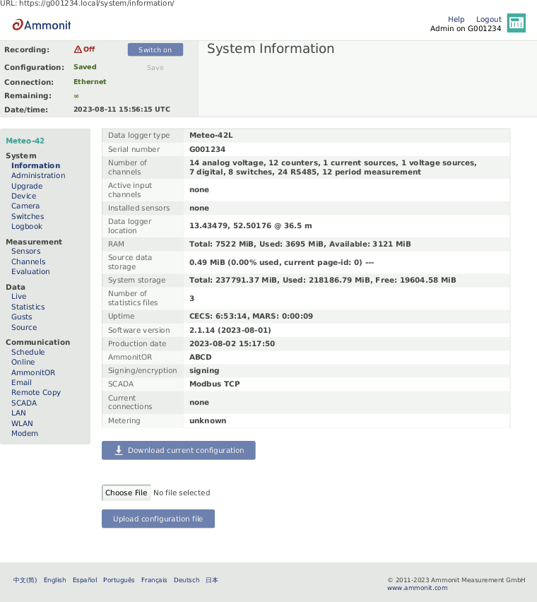
RAM shows the total Random-access memory available to the CECS, how much of it is used and how much is free for system processes. If the free RAM is low (indicated in red), the CECS should be restarted.
Source data storage shows the amount of memory which is already in use for storing source data. Please note that more than 100% is possible. A value beyond 100% means that the data logger is overwriting the oldest source data by storing new data. e.g. 110% means that the oldest 10% has been overwritten.
Metering shows the amount of traffic used by each network interface since the last reset (see Section 4.2, “System Administration”).
Under Current connections all current logins are displayed with IP address, e.g. via LAN, link-local USB or W-LAN (WiFi). Connections established via AmmonitConnect are indicated as such (see Section 7.3, “Configuring Online Access”).
Use Download Current Configuration to download the configuration
file. The configuration file is an INI
file, which is a widely-used file format. This file contains configuration settings
related to modem, Ethernet, server upload, email, data evaluation, SCADA as well as
activated channels and sensors. By downloading a configuration file, the configuration can
be quickly uploaded and applied to other data loggers. The file name is config-Gnnnnnn.txt with nnnnnn as the serial number of the data
logger.
![[Important]](admon/important.png) | Important |
|---|---|
Any settings missing from the configuration file (e.g. because they were added in a newer software version) acquire their default value, except passwords including the modem PIN which are preserved. |
Configuration files are both forwards and backwards compatible.
![[Warning]](admon/warning.png) | Warning |
|---|---|
If the configuration file is from a larger model, e.g. downloading from Meteo-42L and uploading to Meteo-42M, the sensors and evaluations which use channels which the smaller model does not have will be ignored. Be careful with uploading a changed INI file to the data logger. Inconsistencies can lead to malfunctions of the data logger. We strongly advice not to change any entry in the configuration file manually. |
4.2. System Administration
This page contains different administration aspects of the data logger. Only users
logged in as
Admin can access the complete functionality of this section. If you are
logged in as
User,
Viewer or
Guest, changes in the
→ menu are not possible.
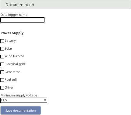
- Data Logger Name:
By giving each Meteo-42 a name, the data loggers can be identified easier. The name appears in the statistics file footer, on AmmonitOR and in the
config.txtfile.Figure 4.2. Assigning a Data Logger Name
![[Note]](admon/note.png)
Note The data logger serial number is the most important ID to identify the data logger. Use the Data Logger Name to give the data logger a custom name, e.g.
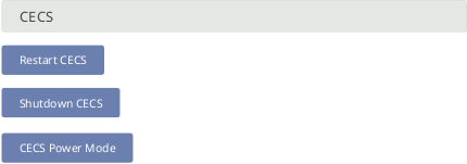
Meteo-42 Site 1.- CECS
To restart the CECS, click on Restart CECS.
To shutdown the CECS, e.g. during remote access, click on Shutdown CECS.
Figure 4.3. Restart or Shutdown CECS
- Date and Time, Location:
Time synchronization of the data logger is a primary concern. Four synchronisation methods are available: GPS, NTP, SCADA and Manually.
In order to synchronize date and time automatically to NTP servers, select NTP (Internet), set date and time.
NTP is a networking protocol that allows clock synchronization between the computer systems. The NTP servers need to be trusted, as they will impose the time on your data logger.
We provide a default set of the NTP servers from the NTP Pool. The NTP Pool is generally very high quality, but it is a service run by volunteers in their spare time. If you wish to change an NTP server, feel free to do so.
We recommend putting at least three trusted NTP servers on the NTP server list. Having less than three can potentially cause problems. If they start to show different times, which one is to be trusted? With at least three servers, it is easy for the device to decide which one shows the current time incorrectly.
The first automatic NTP synchronisation happens two minutes after every CECS boot. If it fails, it tries again again 10 minutes later. If it fails again, it retries 20 minutes later, then 40, and so on. Otherwise it synchronises every six hours to ensure the clock remains accurate.
You can instead choose GPS, set date, time, and location. The GPS device must provide a sentence following the GPRMC NMEA standard (e.g. PHS8-P modem).
The CECS will attempt to get the date, time and location from the satellite according to the same logic as NTP.
The Time zone field may be used to define a fixed UTC offset for the system. Measurements made with the old Time zone are automatically adjusted when read.
The Minimum offset for automatic time adjustments field can be used to only adjust the time when the difference is sufficiently large, so that there are less discontinuities in the measurement data. The Maximum offset for automatic time adjustments field can be used to discard erroneous timestamps from NTP servers and GPS devices. By default, times which differ by more than one minute are rejected during the automatic time synchronisation.
The Minimum offset for automatic location adjustments field can be used to prevent changing the location setting due to GPS accuracy error. The default minimum value of 0.001 ° equals aproximately 111 m.
To manually set the date and time, enter it (format
YYYY-MM-DD hh:mm:sswith optional fractional seconds and UTC offset). If no UTC offset is supplied, the system “Time zone” is used. The button “Use browser time” automatically submits the current browser time.Every date, time and/or location adjustment is logged in the Logbook. Moreover, the current latitude and longitude as well as the time of the GPS adjustment are included in each CSV file's footer.
The "Save" button will save the configuration without synchronising the time. The "Save and synchronise time" button will save the configuration and immediately attempt to synchronise the time, ignoring any minimum and maximum offsets configured. The result of the synchronisation can be seen in the logbook after a few seconds.
Figure 4.4. Configuring Date, Time and Location of the Data Logger
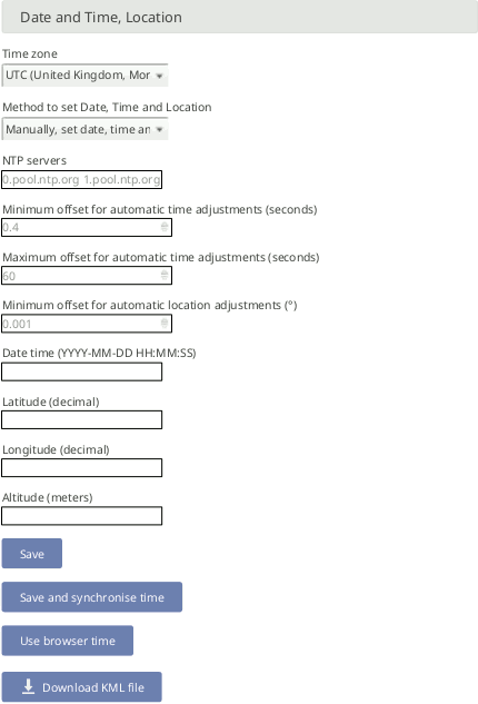
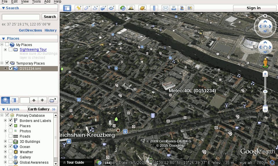
In order to view the data logger location in GIS programs or Google Earth™, you can set the data logger location (not altitude) either automatically via a GPS device, or manually by entering latitude, longitude, and altitude in the appropriate fields. Enter latitude and longitude in the decimal format (
dd.dddddd°), not in degrees and minutes (dd°mm.mmmm′, like GPS) nor in degrees, minutes, and seconds (dd°mm′ss.ss″).After downloading the KML file, you can open the file in Google Earth™.
Figure 4.5. Data Logger Location displayed in Google Earth™
- User Management:
- API App Management:
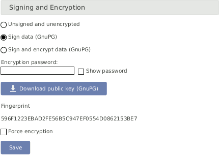
- Signing and Encryption
Files sent by Meteo-42, such as CSV data or logbook files, can optionally be digitally signed or encrypted using the OpenPGP standard. The signature guarantees that the files have been really produced by a specific data logger and have not been altered. The encryption ensures that nobody can see the contents of the files without the correct password.
Figure 4.6. Signing and Encryption
For additional security, an
Adminuser can set the option . If this option is set, users withoutAdminpermissions have only restricted access to measurement data:CSV files can only be downloaded in encrypted form.
CSV files can only be copied to USB flash drive in encrypted form.
Live data can be seen only for 2 minutes on the web interface, but still unlimited on the LC display.
Source data cannot be downloaded nor copied to USB flash drive.
Data transfer settings (AmmonitOR, Email, Remote Copy, SCADA) cannot be changed.
Note The signature for a CSV file refers to the canonical, uncompressed CSV file.
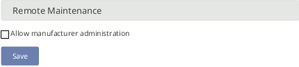
- Allow Manufacturer Administration
In some cases it is necessary that Ammonit developers have access to your data logger to check configurations or to modify any settings. This mode is only used for maintenance purposes. Activate the manufacturer administration mode to allow Ammonit developers accessing your data logger.
By default the manufacturer administration mode is inactive.
Figure 4.7. Allow Manufacturer Administration
Important Without your permission, Ammonit cannot and will never access any of your data loggers!
- Reset Data:
The Disable recording button will cause the MARS to stop recording and prevents it starting automatically as long as the browser keeps the page open. This is useful when the CECS needs to process a lot of source data at once, e.g. generating many statistics files or USB source data copy.
The Reset metering button will reset the network traffic metering counters which are shown on the information page and in the statistics file footer.
In order to delete all measurement data in one step, click on Delete all measurement data. The user will be asked to approve a confirmation prompt. Deleting the measurement data usually takes less than half a minute.
Figure 4.8. Deleting All Measurement Data

Important Recording stops after deleting measurement data. Start recording by clicking Switch on in the status box of the web interface.
In order to delete all configurations, passwords and measurement data, click on Factory reset, delete all data. The data logger will be set back to the condition at delivery. The user will be asked to approve a confirmation prompt before the reset is performed.
Figure 4.9. Factory Reset
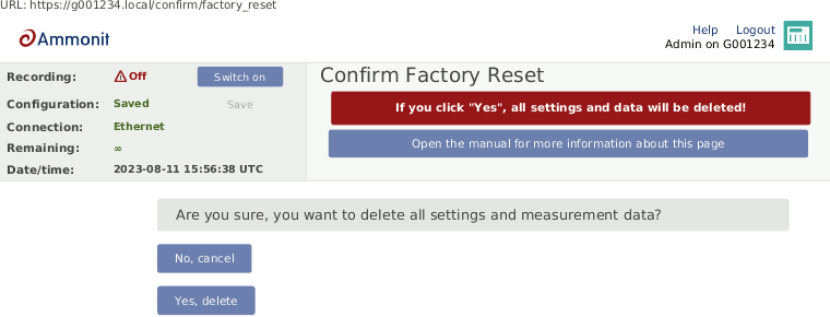
Note After performing a factory reset, recording stops. Recording can be started after at least one sensor has been configured.
The data reset is logged in the Meteo-42 logbook.
4.2.1. User Management
By default there are four user accounts:
Admin,
User,
Viewer and
Guest. Each account has its own level of permissions and access
rights, described in
Table 3.1, “Accounts and permissions”. Here you can change their passwords, delete
any that you do not need, and create new ones.
Figure 4.10. User List
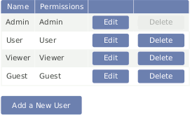
To change a password, click "Edit". To remove an account, click "Delete".
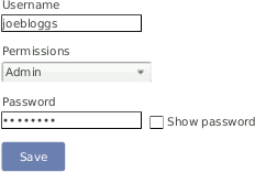
To create new accounts click "Add a New User". You need to set the Username and Password that they will use to log in, and what level of permissions they will have when they do. The rights offered by each level of permissions are described in Table 3.1, “Accounts and permissions”.
Figure 4.11. Add a New User
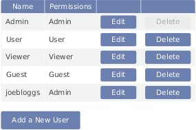
Users created this way will be visible in the list alongside the default users. They can also be changed just like the built-in ones.
Figure 4.12. User List with Custom User
Once created, a user's name cannot be changed. You can achieve the same thing by deleting the user whose name you'd like to change and re-creating it with the correct name.
An Admin cannot delete their own account. To remove the built-in Admin account, you must first create another account with Admin permissions. You can then use that account to remove the built-in Admin.
A deleted account is not logged out immediately. However, all accounts (including deleted ones) are logged out when CECS restarts.
| Warning |
|---|---|
Be aware that due to security reasons it is not possible to reset passwords.
If you lose a modified
|
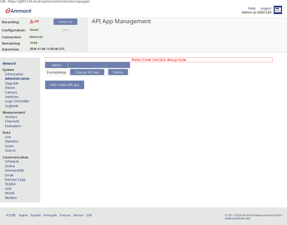
4.2.2. API App Management
In here you can manage which apps will have access to the data logger API.
Figure 4.13. API App Management
You can read in more detail about the API functions in the section Section 7.10, “API”.
To create a new API app access click "Add a New API app". You need to name your app, that will become your app_id. API app names may only contain letters and numbers.
After saving the new API app, a warning message will be shown. It contains your API App Bearer Token, that will be used to authenticate your app. It will only be shown once, so please write it down. In the case that you forget the API App Bearer Token, you need to click on "Change API key" and confirm your change. After that a new API App Bearer Token will be displayed.
Once created, an API app's name (app_id) cannot be changed. You can achieve the same thing by deleting the API app whose name you'd like to change and re-creating it with the correct name.
4.3. Signing and Encrypting Exported Data Files
Digital signature and encryption are very complex topics. By digitally signing an email or a file, its authenticity can be verified. A valid digital signature indicates that the email or file was created by a known sender, e.g. your Meteo-42 data logger (authentication), and the email has not been manipulated on its way to the receiver (integrity). By using encryption, you can encode emails and attachments in a way that third parties cannot read the file, only authorized parties are allowed to open and read the files. A password is required to decrypt emails and files.
Read this section carefully and follow our description step by step to avoid any misunderstandings. For further details about digital signature and encryption, refer to Chapter 14, Cryptographic Software.
Meteo-42 supports the international standard OpenPGP for signing and encryption. Specifically, the free software GnuPG is used. Refer to the GnuPG website for further details.
In the → menu, exported files can be signed or signed and encrypted using OpenPGP.
The selection here applies to statistics, logbook and configuration files exported to AmmonitOR, via remote copy and emails.
- Unsigned and unencrypted
If files should be sent neither with digital signature nor password protected, select this option.
- Sign data (OpenPGP)
Select this option to digitally sign CSV and logbook files. The CSV and logbook files sent by Meteo-42 are signed with a unique digital key. Each data file has a corresponding signature file. The data files can be opened without restriction.
As soon as a signed file is modified, the signature becomes invalid.
In order to verify the data file, download the
Public key, displayed in the Meteo-42 web interface and import the key into your local verification software, e.g. Gpg4win (see Section 4.3.1, “Working with Gpg4win to Decrypt and Verify Files on Windows™ PCs”).- Sign and encrypt data (OpenPGP)
Select this option to sign (as above) and encrypt CSV and logbook files. Enter an Encryption password which is required to decrypt the file on the recipient's side. To do so, additional software is required. See e.g. Section 4.3.1, “Working with Gpg4win to Decrypt and Verify Files on Windows™ PCs”.
To decrypt the data, download the
Public keyby clicking on the button in the Meteo-42 web interface. Import thePublic keyinto your encryption software (see below). The displayedFingerprintis used to authenticate thePublic key.
4.3.1. Working with Gpg4win to Decrypt and Verify Files on Windows™ PCs
In order to open and read files which have been encrypted by Meteo-42, additional software is necessary. We recommend installing GPG4win (GNU Privacy Guard for Windows). Ggp4win enables users to encrypt, decrypt, sign and verify emails and attachments as well as files in a directory. The software includes the following components:
GnuPG: encryption tool
Kleopatra: certificate manager for OpenPGP
GpgOL: add-in for Microsoft Outlook 2003/2007/2010/2013™ for email encryption
GpgEx: plug-in for Microsoft Explorer™ for file encryption
Gpg4win Compendium: documentation for beginners and advanced users
Go to the GPG4WiN website and download the current software version. Install the software with the above mentioned components.
| Note |
|---|---|
If you work with Microsoft Outlook™, the program has to be restarted to implement the GpgOL add-in as separate ribbon. For decryption via the GpgOL add-in, go to Section 7.5.1.2, “Decrypting files in Microsoft Outlook™”. |
Before working with Gpg4win, the software has to be configured. Download the
Public key from the Meteo-42 web interface, as shown in
Figure 4.6, “Signing and Encryption”.
| Important |
|---|---|
Each Meteo-42 data logger has its own unique public key. If you work with different Meteo-42 data loggers, you have to import the public key of each Meteo-42. One user's private key is sufficient to certify the public keys (as shown in Figure 4.16, “Certifying the Public key”). |
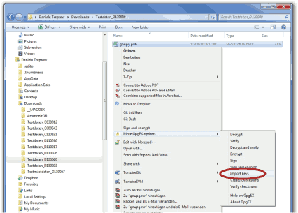
Import the
Public key in Gpg4win via right-mouse click in the
Windows Explorer™. A message is displayed after successfully
importing the key.
Figure 4.14. Importing the Public key into Gpg4win
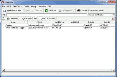
Open the Kleopatra software. The
Public key is listed under
Other Certificates.
The
Public key of the Meteo-42 data logger has to be certified by your
own key. If a user's private key has already been generated, skip the following task
and go on with
Figure 4.16, “Certifying the Public key”.
If no user's private key exists, create a new certificate via the → menu. Select Create a personal OpenPGP key pair and enter the required details. Click Create key and enter a high quality password. Your key should have been successfully created.
Figure 4.15. Creating the private key
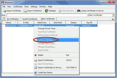
The
Public key of Meteo-42 has to be certified. Go to
Other Certificates and select Meteo-42's key. Open the context menu
via right-mouse click and select
Certify Certificate.
Figure 4.16. Certifying the Public key
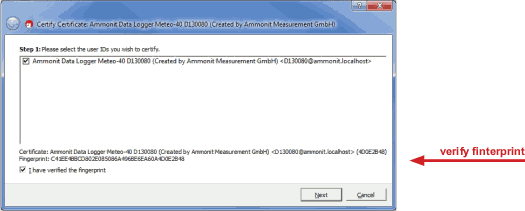
Before trusting the certificate, check the displayed
Fingerprint with the
Fingerprint shown in the Meteo-42 web interface (see
Figure 4.6, “Signing and Encryption”).
Figure 4.17. Verifying the Fingerprint
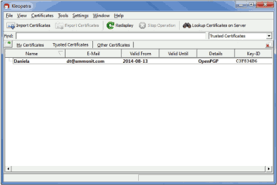
Verify the certificate and enter the password for the
Private key. The password is used to unlock the
Private key for the OpenPGP certificate. Finally both certificates
are displayed under
Trusted Certificates.
Figure 4.18. Trusted Certificates
4.3.2. Verifying digital signatures in the Windows Explorer™
Download and certify the
Public key of Meteo-42 as described in
Section 4.3.1, “Working with Gpg4win to Decrypt and Verify Files on
Windows™ PCs”.
Download both related files to your directory. Choose the data or logbook file,
which should be verified. Open the context menu with a right-mouse click on the
.csv.gz,
.log or
.sig file and select
Verify.
Figure 4.19. Verifying signed files
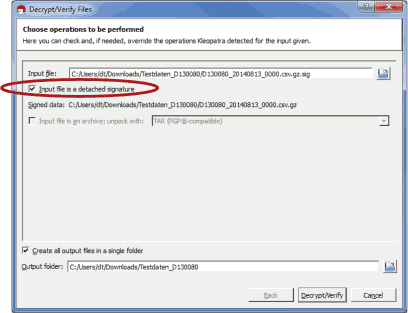
Make sure that
Input file is a detached signature is selected. Both related files
should be listed, with the signature ending on
.sig in the
Input file field. Select
Decrypt/Verify. After verification the Kleopatra software
indicates the validity of the signature.
Figure 4.20. Successfully verified signature

4.3.3. Decrypting files in the Windows Explorer™
Download and certify the
Public key of Meteo-42 as described in
Section 4.3.1, “Working with Gpg4win to Decrypt and Verify Files on
Windows™ PCs”.
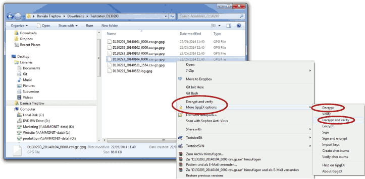
Encrypted files can be decrypted in the Windows Explorer™. Right click on the file and select Decrypt and verify.
Figure 4.21. Decrypting files via the GpgEx plug-in for Windows Explorer™
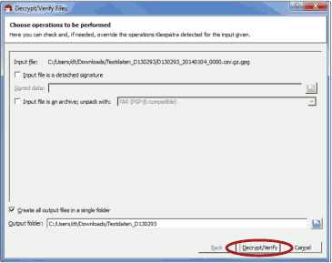
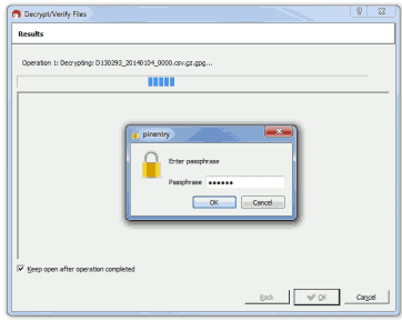
Start the decryption process by clicking Decrypt and verify.
Figure 4.22. Decryption via Kleopatra Software
For decryption enter the password, which you entered for encryption in the Meteo-42 web interface in the → menu.
Figure 4.23. Password Prompt for Decryption
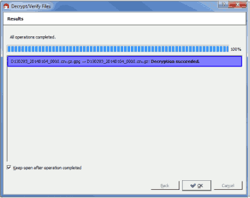
After successful decryption the file is displayed in the initial folder or the one selected in the decryption process.
Figure 4.24. Successful File Decryption
4.4. Upgrade Data Logger Software
The development of Meteo-42 is an ongoing process. Ammonit is constantly adding new features to the data logger to better meet the needs of the user.
| Important |
|---|---|
In order to perform a software upgrade, the data logger has to be connected to the Internet, e.g. via modem or LAN or using the tethering function of a mobile phone (Section 4.4.1, “Upgrade using a Smartphone”). It is not sufficient to connect Meteo-42 to a PC over USB, because a PC is not necessarily configured to work as a router. You have to be logged in as
Make sure, that the date and time of the data logger is set correctly. If the data logger date and time is too far in the past or in the future, the upgrade will not work. If you do not have an Internet connection, you may upgrade the data logger offline, using a USB flash drive. See Section 4.4.3, “Offline Upgrade using USB Flash Drive” for details. |
- Enable peripheral device driver upgrades:
Peripheral device drivers are not upgraded by default because they can be quite large, exceeding 50 MiB. We recommend leaving this disabled if the network connection is expensive, e.g. satellite modem. They are only relevant if you are using peripherals such as Wi-Fi access point dongles (see Section 7.8, “Configuring WLAN”). If the peripheral is newer than your Meteo-42, you may need to upgrade the drivers to support it.
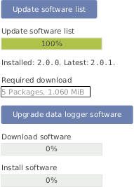
- Update software list:
In this step the data logger browses for updates and displays the number of available software packages. Below the progress bar the currently installed version is displayed; the latest version describes the available upgrade.
Note The new software itself will not be downloaded and installed after clicking on Update software list. The software version is not changed in this step!
Figure 4.25. System Upgrade
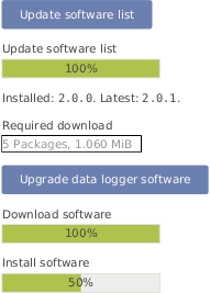
- Upgrade data logger software:
The software upgrade can easily be performed by pressing the Upgrade data logger software button. The software packages will be downloaded and installed.
After the installation is completed, CECS is restarted.
Important Before upgrading the data logger via modem, make sure that the corresponding switch is configured correctly in the → menu of the data logger web interface.
Depending on the installed firmware version, the software packages needed for the upgrade can be large. So the download and installation process can take some time depending on the speed of your Internet connection.
In rare cases the progress bar in the Meteo-42 web interface may stop. Reload the page and wait. If the progress bar does not move several minutes, we recommend restarting the upgrade process.
Do not disconnect the power supply or reboot the system during the whole upgrade process.
Figure 4.26. System Upgrade
4.4.1. Upgrade using a Smartphone
The Meteo-42 data logger can only be upgraded when it is connected to the Internet.
By connecting your smartphone to the data logger, you can set up an Internet connection via the tethering function of the smartphone.
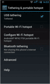
Connect your smartphone to the USB-A slot of the Meteo-42. Make sure that the data logger has no Ethernet LAN connection during the procedure. If in doubt just unplug the Ethernet cable from the data logger. Open the settings for Tethering and portable hotspot of the smartphone operating system (see Figure 4.27, “Tethering Settings of an Android™ smartphone”) and activate USB tethering.
| Important |
|---|---|
Before starting the upgrade via tethering, make sure that Use DHCP for wired network is selected in the → menu of the Meteo-42 web interface. Additionally, make sure Connect to Internet via modem only is not selected in the → menu of the Meteo-42 web interface. See Figure 7.15, “Configuring LAN parameters” for an example. |
Browse at Meteo-42 display for the IP address using the keys ( → → → → ). Enter the data logger's IP address in your smartphone browser, login and perform the upgrade.
Figure 4.27. Tethering Settings of an Android™ smartphone
![[Tip]](admon/tip.png) | Tip |
|---|---|
The tethering function can also be very useful for remote servicing. You might need to start an online action over the display in order to establish the connection via AmmonitConnect for remote access (see Section 4.5.1, “Display Access”). |
4.4.2. Software Upgrade Behind a Firewall
For most firewalls that allow outgoing
HTTPS and
HTTP traffic, no special configuration is needed. Only in some very
restrictive environments, you may need to configure your firewall for the Meteo-42
software upgrade or ask your network administrator to do so. If Meteo-42 is in a
separated sub-net, you may also need to specify a
Gateway in the LAN settings of the data logger.
Meteo-42 needs to connect the server
archive.ammonit.com via
HTTPS (port 443)
as outbound connection to perform a
software upgrade. Make sure, that these connections are allowed. There is no need for
Meteo-42 to connect any other servers, use any other protocols or use any kind of inbound
connections.
4.4.3. Offline Upgrade using USB Flash Drive
| Warning |
|---|---|
Note, that this method is not the preferred software upgrade method. If possible, please use the online upgrade method. Make sure, you have saved all your data and your configuration before performing an offline upgrade. |
4.4.3.1. Prepare the Offline Upgrade
Make sure that all relevant data from data logger is saved: Configuration file, CSV files, and, if necessary, source data.
Make sure the software version you will upgrade to is actually newer than the software version already installed on the data logger. Downgrades are not supported. Always use the latest offline update image from Ammonit, because errors of older versions might be fixed!
Download the latest version from here and unpack the zip archive. You will need the meteo-42.bin image file.
You need a prepared USB flash drive of at least
2 GiBcapacity. The flash drive must formatted asFAT32. The image file must be placed in the top-level of the flash drive, not in a directory. Further information is in theREADME.txtfile.
4.4.3.2. Performing the Offline Upgrade
Switch off the CECS of the data logger. In doubt, remove the power supply.
Plug the prepared USB flash drive into one of the two USB-A slots of the Meteo-42.
If necessary, reconnect the power supply of the data logger. Switch on the CECS.
You will see the following text on the LC display:
Figure 4.28. Press the right arrow button
    Found image
  for USB upgrade.
 Press the > button
     to proceed.
You have to press the right arrow button within ten seconds, otherwise the boot process continues normally and no upgrade will be performed.For around half a minute, the following message appears:
Figure 4.29. Reading the image
      Reading
     image for
    USB upgrade.
   Please wait...
Warning After that step interrupting the process, unplugging the USB flash drive, or a power failure can lead to an non-functional data logger!
The complete process takes about ten to fifteen minutes, until the following message appears:
Figure 4.30. Successful upgrade
      SUCCESS:
 Remove power plug,
    wait 3s, and
  remove USB drive.
which should be performed accordingly: Remove the power supply of the data logger, remove the USB flash drive, wait at least three seconds, and plug-in again the power supply of the data logger.
4.5. The Device Page
4.5.1. Display Access
The display page shows, what can be seen on the LCD.
Figure 4.31. Remote Display

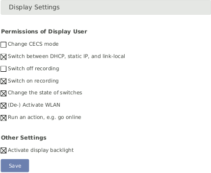
In order to give users without access to the web interface the chance of configuring the data logger, some permissions for display users can be selected, e.g. switch on recording or (de-)activate WLAN.
If the corresponding permission Run an action is set, you can also start the execution of an action over the display menu → . Select one of the actions and press the right button to start it.
Figure 4.32. Display Settings
| Note |
|---|---|
To view the display in the web interface, it is advised to enable JavaScript in your web browser. |
4.5.2. Connected USB Devices
Also on the device page, you can find a list of the USB devices, that are currently connected to the data logger and recognized by it, e.g. a modem, a flash drive, or a camera.
| Note |
|---|---|
The list of devices is not updated automatically. You have to reload the page to see any changes. |
4.5.3. USB Flash Drive Copy
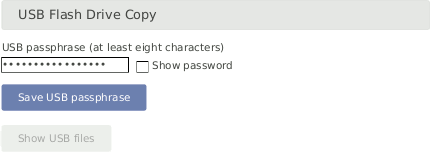
Meteo-42 offers the possibility to download created CSV statistics files with measurement data (statistics see Section 6.3, “Statistics Data Files”), the source data in CSV format, and/or the logbook in CSV format on a USB flash drive which is connected to the data logger. Before you use this function, data logger and USB flash drive have to be configured.
Figure 4.33. Configuring the USB Flash Drive Copy
| Important |
|---|---|
A file system like FAT32, NTFS, ext4, ext3, or ext2 is required on USB flash drive. |
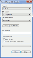
In order to format the USB flash drive with FAT32 on your
Windows™ PC, connect the USB flash drive to the PC.
Open the
Windows™ Explorer. Right-click on the USB flash drive
shown under
Computer. Click on
Format... and select
FAT32 as
File system.
Start the formatting process.
Figure 4.34. Formatting the USB flash drive (Windows™ PC)
Create a INI file named
keyfile.txt, which has to be saved on the USB flash drive used to
download CSV files (statistics and/or source data). This INI file must include the data
logger serial number and a password in a the INI file format. The INI file is necessary
to prevent unauthorized access to data. Example:
[D123456]
password = yoursecretpassword
statistics = all
| Note |
|---|---|
The passphrase for the USB flash drive must have at least 8 characters! |
The passphrase has to be entered in the field shown in Figure 4.33, “Configuring the USB Flash Drive Copy”.
It is possible to use one USB flash drive for several data loggers. To do so, in
the
keyfile.txt the details of the data loggers have to be entered
section by section, e.g.
[D123456]
password = passwordone
statistics = since 2016-01-01
gustdata = since 2016-01-01
config = save
logbook = all

[D234567]
password = passwordtwo
statistics = newest 10
config = save
sourcedata = all

[D345678]
password = passwordthree
statistics = month 2016-01
config = save
sourcedata = day 2016-01-07
The following entries are possible:
- password
Mandatory, must have at least eight characters
- statistics
One of the time period values, see below. Copies the primary statistics files.
- secondary
One of the time period values, see below. Copies the secondary statistics files.
- tertiary
One of the time period values, see below. Copies the tertiary statistics files.
- config
Value
saveto copy the configuration file. Other values are not yet implemented.- logbook
One of the time period values, see below.
- gustdata
One of the time period values, see below.
- sourcedata
One of the time period values, see below.
Warning Copying source data may take a very long time, even some hours.
- stop_recording
Value
yesto stop recording while copying source data. By default, Meteo-42 keeps recording while copying source data. With this entry, it is much faster since the hardware does not need to read and write at the same time. It is intended for back-ups after the measurement campaign is finished.
The time period values are:
- all
Copy all files of this type.
- since DATE
Copy files of this type since and including DATE in format YYYY-MM-DD.
- until DATE
Copy files of this type until and including DATE in format YYYY-MM-DD.
- month DATE
Copy files of this type in the month of DATE in format YYYY-MM.
- day DATE
Copy files of this type at the day of DATE in format YYYY-MM-DD.
- newest NUMBER
Copy newest files of this type, max. NUMBER.
- oldest NUMBER
Copy oldest files of this type, max. NUMBER.
Meteo-42 has to be switched on for download. If the USB flash drive is configured
correctly, it will be recognized by the data logger. If the passphrase entered in the
web interface and in the
keyfile.txt does not match data download is not possible.
Meteo-42 shows in its display the number of downloaded files. When the download is finished, the data logger menu is shown and the USB flash drive can be disconnected.
All data files are compressed to keep them as small as possible.
| Note |
|---|---|
If encryption and/or digital signature is switched on for the data logger, copying to the USB flash drive behaves accordingly, i.e. data will be encrypted and/or signed. |
This feature can also be scheduled to run automatically (see Section 7.2, “Configuring the Communication Schedule”). In that case, when the USB drive is full, you can replace it with an empty one but use the "newest N" directive to avoid copying everything again.
4.5.4. Show USB Files
This page shows the files corresponding to the data logger on the attached USB stick and allows them to be downloaded and deleted.
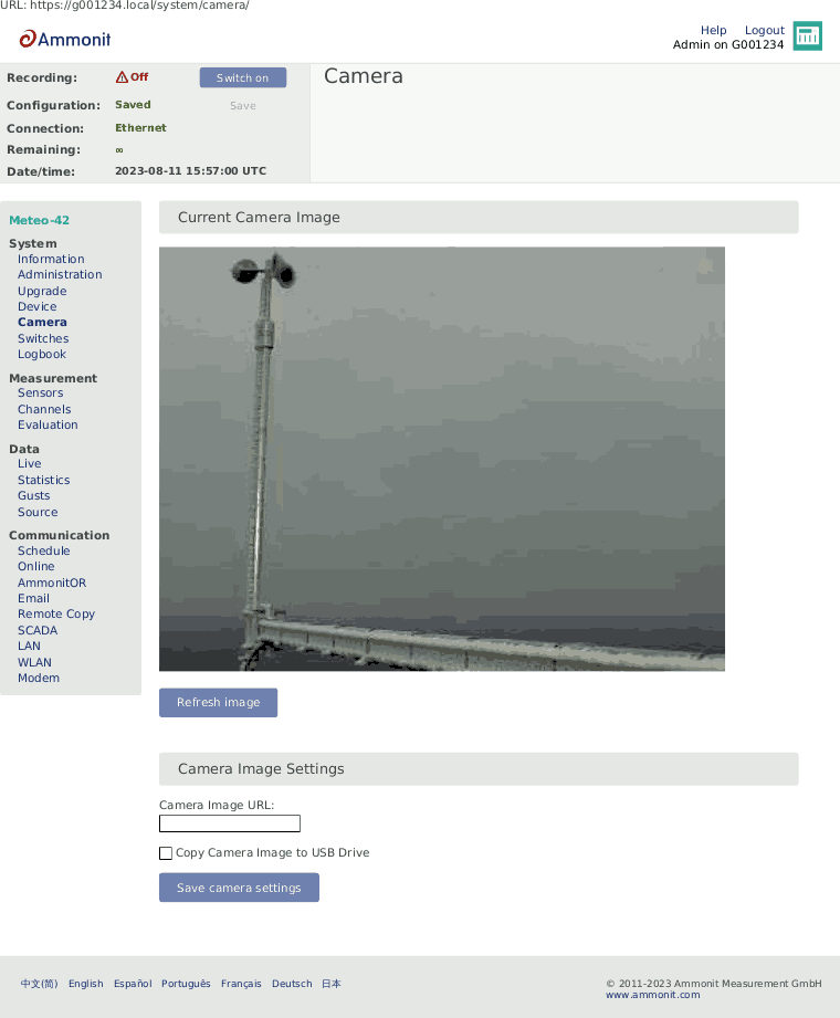
4.6. Using a Camera
You can take pictures with Meteo-42 and send the image to AmmonitOR, as an email attachment, copy it to an SCP/FTP/SFTP file server or copy it to a permanently connected USB flash drive. Each of these options must be individually configured. See the corresponding check-boxes in the → , → , and → sub-menus.
You can either use a USB webcam plugged into one of the two USB-A slots or an Ethernet connected camera by HTTP/HTTPS.
Figure 4.35. Camera Image
| Note |
|---|---|
If the camera should be used for monitoring purposes, a steady power supply has to be connected. |
4.6.1. Camera Configuration
To use an outdoor camera connected to the Meteo-42 you must configure it in the → menu.
Just enter the URL of the photo in the web interface. The URL depends on the
installed camera, e.g. http://
or nn.nn.nn.nn/https:// . Mobotix M25M
camera image URL typically is
nn.nn.nn.nn/http://10.13.0.197/record/current.jpg.
Figure 4.36. Attaching Camera Images
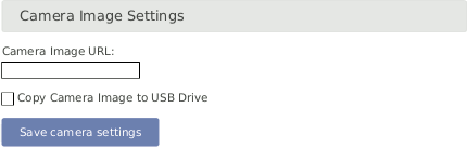
If the option Copy Camera Image to USB Drive is selected and a
USB drive is connected to the data logger, the image will be copied to the USB device
whenever any of the scheduled actions run (see also Section 7.2, “Configuring the Communication Schedule”). The files can be downloaded or deleted (see also Section 4.5.4, “Show USB Files”).
If you connect the camera via Ethernet, it is recommended to use static IP
addresses. You must configure both the camera and Meteo-42, each with a different address
in the same network. E.g.
10.13.0.197 for the camera and
10.13.0.200 for the data logger. In this case, the net-mask would be
255.0.0.0. DNS server and gateway are not relevant here.
The static IP address of Meteo-42 can be configured in the → menu (see Section 7.7, “Configuring LAN Parameters”). In order to configure the IP address of the camera use the software delivered with it.
If LAN online, whenever CECS is on has been disabled, the Ethernet port may be inactive. This means you might not see an image on accessing the → menu (see Section 4.6, “Using a Camera”) menu. You will know if the Ethernet interface is active because it will appear at the connections list in the status box of the web interface.
If you want the Ethernet port to be always active despite the higher power consumption, you can configure it in → menu (see Section 7.7, “Configuring LAN Parameters”).
| Important |
|---|---|
If a USB modem is connected to Meteo-42 and Ethernet is used for the camera, it
is necessary to select
|
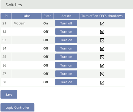
4.7. Configuring Switches
Switches can be used to control and optimize the power consumption of the measurement system. External devices connected to Meteo-42, such as modem, camera or heating can be controlled via the data logger. Meteo-42 will close (turn on) the configured switch when the corresponding device is needed, e.g. to send data via the modem connection, and open it again (turn off) when not needed.
In a solar power plant, a switch can be used to orient the solar trackers for protection of the payloads in case of high wind.
Meteo-42L data logger provides eight switches intended for the following tasks:
Control the modem power supply (recommended). See Section 7.9, “Configuring the Modem” for GSM and Section 7.7, “Configuring LAN Parameters” for satellite.
Control camera power supply. See Section 7.7, “Configuring LAN Parameters”.
Control of the selected switch according to the configured conditions in the Logic Controller.
A switch can only fulfil one of the duties.
To manually toggle one or more of the switches individually, go to the → menu.
If the option Turn off on CECS shutdown is selected for a switch,
the switch will be turned off on CECS shutdown. This is the default
behaviour for all switches. If a switch is turned on manually or by the Logic Controller,
and you want this state to be held, despite the CECS shutting down, you
can deselect the option for the corresponding switch. If a switch is associated to Modem or
LAN, this option is not available and it will always be turned off if
CECS is not running.
Figure 4.37. Switch Configuration
| Warning |
|---|---|
We highly recommend configuring a switch for the modem in the → menu. If the modem is switched manually via the → menu, you risk the shutdown of the modem after rebooting the data logger or after problems with the power supply. Switch S1 is assigned to the modem by default. In case the switch is not used for the modem, it can be deselected. |
| Note |
|---|---|
Refer to Chapter 13, Electrical Connection Plans for more information about physically connecting the supply using a switch. |
4.8. Logic Controller
Meteo-42 Logic Controller replaces the previous Switch Manager,
introducing much more flexibility.
Typical use cases are the control of a sensor's heating by
means of a switch or activating an alarm (E-Mail, SMS, AmmonitLive App Notification),
depending on measured values and time of day.
| Note |
|---|---|
Existing |
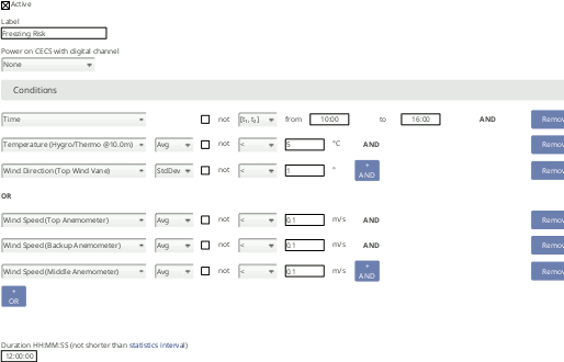
The Logic Controller enables you to configure several trigger
conditions and associate them with a series of actions. The association between
conditions and actions is called a Rule.
Up to ten independent rules are available to be freely
configured.
Figure 4.38. Logic Controller Rules
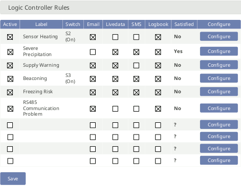
The Logic Controller overview displays the list of rules. Rules themselves or their actions can be activated/deactivated from this menu. In the Satisfied column, the current state of every active rule is shown. This state is newly determined at the end of every statistics interval. The statistics interval is shared between Live Data, Logic Controller and SCADA and can be configured in the → menu. The default statistics interval is 10 min.
Figure 4.39. Logic Controller Helper
With the Power on CECS with digital channel option, it is possible
to select a digital channel for each rule, in order to power on the CECS
processor by applying a voltage peak (see also Section 12.2.3, “Electrical Specifications of Digital Channels (Serial Input / Output)”). If the
CECS is turned on by a digital channel associated to a rule, the rule
actions will be executed as soon as the CECS is fully booted.
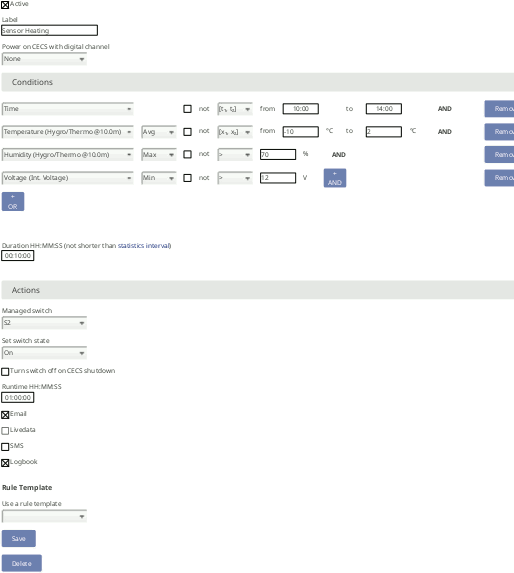
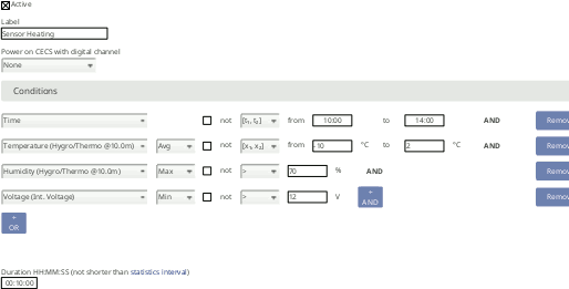
Some rule templates are available to help with the configuration of a new rule. These set some widely used parameters, which can still be edited. E.g. heating or supply warning.
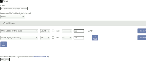
A condition is composed of a trigger event, a comparison operator and a value (or two if required). The trigger of a condition can be the time of the day or a measurement evaluation. In the second case, one of the available statistics must be selected (see Section 6.3.1.1, “Statistics Selection” to change available statistics). Comparison operators are some of the following, depending on the selected trigger: in range ([t1, t2] for time or [x1, x2] for others), greater than (>), less than (<), greater than or equal to (>=), less than or equal to (<=), equal to (==). Several conditions can be combined in one rule by means of the logical operators and and or. Two levels of logical nesting are supported (and-or). The condition duration specifies the minimum required time of fulfilment of the condition.
| Note |
|---|---|
The condition duration must not be shorter than the statistics interval for Logic Controller, otherwise it will be automatically corrected. An exception is a condition duration of "00:00:00". In that case, the actions will be executed instantly at the end of the statistics interval where the condition is satisfied. |
Actions are tasks that will be automatically executed when the conditions are satisfied. Several actions can be selected for one rule.
Available actions
Set switch: set selected switch to the configured state for the configured action runtime.
Email: send an email using the parameters configured in → .
Livedata: send a notification to the Allowed subscribers in → .
SMS: send a short message using the parameters configured in → .
Logbook: write a note to the → .
A switch can be selected for each rule, to be toggled as an action. Only switches which are not configured for other duties are listed (see Section 4.7, “Configuring Switches” for more information). The custom rule label will be shown in the → list.
If a switch was selected, it will be set to the state selected in the Set
switch sate field, as soon as the rule is satisfied for the required duration. If
the rule is not satisfied, the switch will be toggled to the opposite state.
The action runtime determines the minimum time that the configured
switch state will be held. Conditions are newly evaluated at the end of every statistics
interval. The state will remain, as long as the condition is satisfied.
If the option Turn switch off on CECS shutdown is selected, the
configured switch will remain off as long as the CECS is turned off. This
was the only available behaviour in versions before 2.3.0. If the option Turn
switch off on CECS shutdown is not selected, the state of the switch will be held
on CECS shutdown. If the CECS is turned off, the
action runtime will have no effect. As soon as the CECS boots again, and
after the statistics interval is elapsed, the conditions will be evaluated and the switch
will be toggled if required.
| Important |
|---|---|
It is recommended to keep the CECS always on if the Logic Controller is deployed. The state of the rules can only be determined and the actions can only be executed if CECS is running, i.e. during the execution of an scheduled action (see Section 7.2, “Configuring the Communication Schedule”) or if CECS is configured to be always on (see Section 4.2, “System Administration”). |
To use Livedata notifications, you must select a Livedata server and add at least one subscriber. You can for example create an account on Ammonit Live Dashboard and subscribe to get the notifications at your browser or smartphone. You can also select to publish live data to server in order to visualize current live data at Ammonit Live Dashboard.
4.8.1. Use cases
Sensor heating
Figure 4.40. Heating control
If the sensor heating should be supplied by an external power supply via relay, check the connection plan Figure 13.14, “Electrical Connection Plan: Switch external Sensor Heating via Meteo-42 Switch Manager”.
Severe precipitation alarm
Figure 4.41. Precipitation alarm

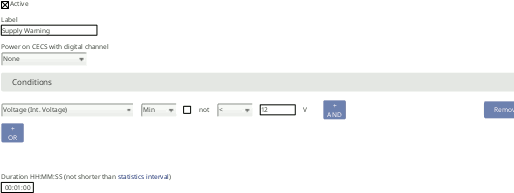
Low power supply
Figure 4.42. Power supply
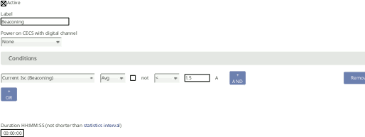
Beaconing
Figure 4.43. Beaconing
Freezing detection
Figure 4.44. Freezing detection
RS-485 sensors communication problems
Figure 4.45. RS-485 communication problems
4.9. Using the Logbook
Events which are not related to measurement data are listed in the logbook. The logbook displays for example all user logins and the user's IP address. A calendar is shown with a monthly overview. Blue highlighted boxes indicate days with logbook entries. By clicking on the day, the entries are displayed. Click on the arrows shown above the calendar to go to the previous or next month.
It is also possible to add entries to the logbook, e.g. to record replacements of sensors or any maintenance work that is important for data interpretation. Add messages by clicking on Log a message. A short text message can be entered.
Logbook entries of a day can be downloaded by clicking on the Download buttons.
Figure 4.46. Logbook
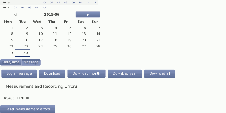
MARS errors are indicated by the red LED (second from bottom). A detailed list containing error codes is reported below Measurement and Recording Errors. By clicking on Reset Measurement Errors the list of errors can be deleted.
| Note |
|---|---|
The MARS error codes can be important for Ammonit engineers to identify errors in the data logger. |
4.9.1. Logbook Events
The following actions or events are logged to the logbook:
User note to logbook
Log in of a user or failed login attempt
Factory reset
Memory format
Configuration file upload
Setting date and time via GPS, NTP, EKO sun tracker, SCADA or Admin (manually)
Setting location via GPS or EKO sun tracker
Copying CSV files in any of the following ways: to USB flash drive, via Email, Remote Copy or AmmonitOR upload.
Software upgrade
Password reset by manufacturer
CECS start/stop
Actions execution and errors
Actions initiated by a short message (SMS)
RS-485 Serial Interface communication
Ammonit Soiling Measurement Kit normalization reference values
Logic Controller rules state changes